Solved according to the ttt diagram shown, what are the Schematic ttt diagram for a metallic glass former.: i, ii and iii Ttt slideshare
TTT Diagram | PDF | Annealing (Metallurgy) | Heat Treating
[solved] the iron-carbon diagram and the ttt curves are determined
Solved 1. use the ttt diagram below to show to show the heat
Schematic ttt diagram for a metallic glass former.: i, ii and iiiSchematic ttt curve and variation of cooling rate for different melt Ttt diffractograms pgfCct occurs vitrification melt thermoplastic.
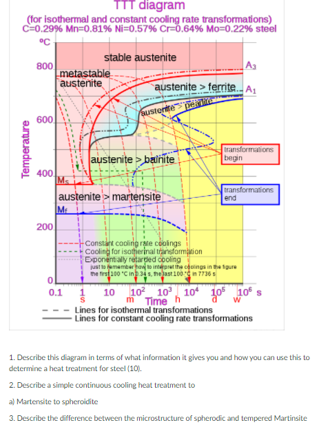
Schematic time-temperature-transformation (ttt) diagram showing directSolved the ttt-diagram and glass 1100 2141271,2,cu.2.ni...be Solved ttt diagram (for isothermal and constant cooling rateCooling rate dependence of the glass transition temperature t g and.
Ttt diagram
Dependence of glass-formation range on the cooling rate mapped on theTtt casting glass tpf crystallization whereby generate route Kinetic approach to glass formationGlass transition temperature t g vs the cooling rate. the solid line is.
Solved glass (15 p)in below picture, theVisualization of the critical scanning rates. schema of the critical Ttt diagramGlass transition temperature as a function of the cooling rate. the.

Dependence of glass transition temperature on cooling rate. ͑ a ͒
Schematic cct diagram for a metallic glass former. vitrification occurs1 schematic ttt diagram. the critical cooling rate for glass formation A) ttt curve for the pgf glass; b) x-ray diffractograms of the glassTtt diagram.
Difference between ttt and cct diagramCritical cooling rate versus reduced glass transition temperature t rg 2. the temperature-time-transformation (ttt) schematic of a metallicTtt metallic.

Panel (a): glass transition temperature (t g ) versus cooling rate (γ t
Solved 2- using the following ttt diagram, identifyFigure s1. cooling rate dependence of various glass properties. (a Solved question 12 1. the following is a ttt diagram forTtt diagram (for isothermal and constant cooling rate.
Metallurgy glossary .


![[SOLVED] The iron-carbon diagram and the TTT curves are determined](https://i2.wp.com/storage.googleapis.com/tb-img/production/18/09/TTT Diagram.png)


